
Page 40 - RESIDEO - HONEYWELL HOME - CATALOGO RESIDEO
P. 40
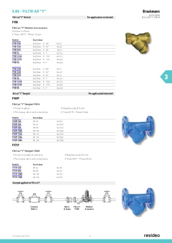
3.06 - FILTRI AD “Y”                                                                       Braukmann
                                                                                                        ADDUZIONE
          Filtri ad “Y” filettati                            Per applicazioni residenziali         DELLA RETE IDRICA
         FY30
         Filtri ad “Y” filettati internamente
         • Corpo in ottone
         • Tmax 160 °C - Pmax 16 bar

         Modello        Descrizione
         FY30-3/8A      Da 0,35 mm   - R = 3/8”   - Kvs 2,1
         FY30-1/2A      Da 0,35 mm   - R = 1/2”   - Kvs 3,8
         FY30-3/4A      Da 0,35 mm   - R = 3/4”     - Kvs 7,1
         FY30-1A        Da 0,35 mm   - R = 1”      - Kvs 11,6
         FY30-11/4A     Da 0,35 mm   - R = 1 1/4”   - Kvs 17,2
         FY30-11/2A     Da 0,35 mm   - R = 1 1/2”   - Kvs 24,0
         FY30-2A        Da 0,35 mm   - R = 2”       - Kvs 40,0

         FY30-3/8B      Da 0,18 mm   - R = 3/8”      - Kvs 2,1
         FY30-1/2B      Da 0,18 mm   - R = 1/2”      - Kvs 3,8
         FY30-3/4B      Da 0,18 mm   - R = 3/4”     - Kvs 7,1                                                      3
         FY30-1B        Da 0,18 mm   - R = 1”       - Kvs 11,6
         FY30-11/4B     Da 0,18 mm   - R = 1 1/4”   - Kvs 17,2
         FY30-11/2B     Da 0,18 mm   - R = 1 1/2”   - Kvs 24,0
         FY30-2B        Da 0,18 mm   - R = 2”       - Kvs 40,0

          iltri ad “Y” flangiati                              Per applicazioni industriali
         FY69P
         Filtri ad “Y” flangiati PN16
          • Corpo in ghisa                 • Magliatura da 0,5 mm
          • Per acqua, olio e aria compressa  • Tmax 85 °C - Pmax 16 bar

         Modello        Descrizione
         FY69P-50A      DN = 50         - Kvs 61,0
         FY69P-65A      DN = 65         - Kvs 107,0
         FY69P-80A      DN = 80         - Kvs 151,0
         FY69P-100A     DN = 100        - Kvs 190,0
         FY69P-125A     DN = 125        - Kvs 297,0
         FY69P-150A     DN = 150        -Kvs 378,0
         FY69P-200A     DN = 200        - Kvs 700,0
         FY71P

         Filtri ad “Y” flangiati PN40
          • Corpo in acciaio al carbonio      • Magliatura da 0,5 mm
         D15S Pressure Reducing Valve         • Tmax 85°C - Pmax 40 bar
          • Per acqua, olio e aria compressa

         Method of Operation
         Modello
                        Descrizione
         FY71P-65B      DN = 65         - Kvs 107    The inlet pressure has no influence in either opening or closing of
         Spring loaded pressure reducing valves operate by means of a
         force equalizing system. The force of a diaphragm operates   the valve. Because of this, inlet pressure fluctuation does not
         FY71P-80B      DN = 80         - Kvs 151    influence the outlet pressure, thus providing inlet pressure
         against the force of an adjustment spring. If the outlet pressure
         FY71P-100B     DN = 100 because water is drawn, the   balancing.
                                        - Kvs 190

         and therefore diaphragm force fall
         FY71P-150B     DN = 150        - Kvs 378
         then greater force of the spring causes the valve to open. The
         outlet pressure then increases until the forces between the
         diaphragm and the spring are equal again.
          Esempio applicativo Filtro A Y
         Installation Example
                      Contatore               Valvola  Filtro a Y  Riduttore
                        1
                      Woltman                 di ritegno 2  FY69P 3  di pressione  5
                                                             4
         Figure 1:  Installation example
         1  Shut-off device
         2  Check valve
         3  Strainer
         4  Pressure reducing valve
         5  Shut-off valve


                    DN
          Catalogo prodotti 2022  65  80  100  150  200        41
          Connection size
                    Inch   2 1/2“  3“   4“    6“    8“
          W 1       mm      120   130   145   200   230
         1. Minimum distance from wall to centre line of pipework
         Installation Guidelines               Typical Applications
         •  Install in horizontal pipework with spring bonnet directed   Pressure reducing valves of this type are suitable for multi
           upwards                             dwelling buildings, industrial and commercial applications within
         •  Install shut-off valves            the range of their specifications.
         •  The installation location should be protected against frost   The pressure reducing valve should be installed, if one or more
           and be easily accessible:           of the following conditions apply:
           - Pressure gauge can be read off easily
           - Simplified maintenance and cleaning  •  The static pressure exceeds the maximum permissible value
         •  Install downstream of the filter or strainer. This position   •  for the system.
                                                 Several pressure zones are required when a pressurisation
           ensures optimum protection for the pressure reducing valve   system is used (pressure reducers on each storey of a
           against dirt.
         •  Provide a straight section of pipework of at least five times the   building).
           nominal valve size after the pressure reducing valve (in   •  Pressure fluctuations in the downstream system must be
           accordance with DIN EN806 part 2)     avoided.
                                               •  To achieve constant inlet and outlet pressures on pumped
                                                 pressure boosting systems.
                                               •  To reduce the water consumption.


         2   http://ecc.emea.honeywell.com                    EN0H-1049GE23 R0815 • Subject to change