
Page 242 - BELLOSTA RUBINETTERIE - CATALOGO GENERALE
P. 242
INFO TECNICHE LIFE
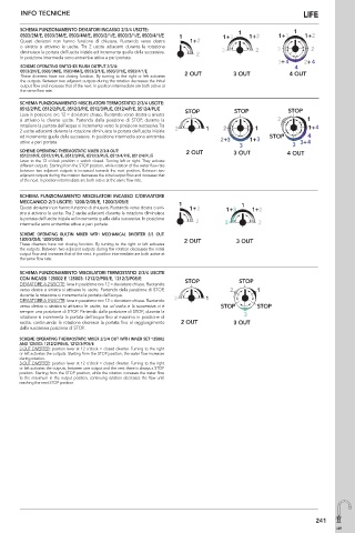
SCHEMA FUNZIONAMENTO DEVIATORI INCASSO 2/3/4 USCITE:
0503/2M/E, 0503/3M/E, 0503/4M/E, 0503/2/1/E, 0503/3/1/E, 0503/4/1/E
Questi deviatori non hanno funzione di chiusura. Ruotando verso destra
o sinistra si attivano le uscite. Tra 2 uscite adiacenti durante la rotazione
diminuisce la portata dell’uscita iniziale ed incrementa quella della successiva.
In posizione intermedia sono entrambe attive a pari portata.
SCHEME OPERATING SWITCHES FLUSH OUTPUT 2/3/4:
0503/2M/E, 0503/3M/E, 0503/4M/E, 0503/2/1/E, 0503/3/1/E, 0503/4/1/E
These diverters have not closing function. By turning to the right or left activates
the outputs. Between two adjacent outputs during the rotation decreases the initial
output flow and increases that of the next. In position intermediate are both active at
the same flow rate.
SCHEMA FUNZIONAMENTO MISCELATORI TERMOSTATICI 2/3/4 USCITE:
0512/2/P/E, 0512/2/PL/E, 0512/3/P/E, 0512/3/PL/E, 0512/4/P/E, 0512/4/PL/E
Leva in posizione ore 12 = deviatore chiuso. Ruotando verso destra o sinistra
si attivano le diverse uscite. Partendo dalla posizione di STOP, durante la
rotazione la portata dell’acqua si incrementa verso la posizione successiva.Tra
2 uscite adiacenti durante la rotazione diminuisce la portata dell’uscita iniziale
ed incrementa quella della successiva. In posizione intermedia sono entrambe
attive a pari portata.
SCHEME OPERATING THERMOSTATIC MIXER 2/3/4 OUT:
0512/2/P/E, 0512/2/PL/E, 0512/3/P/E, 0512/3/PL/E, 0512/4/P/E, 0512/4/PL/E
Lever to the 12 o’clock position = switch closed. Turning left or right. They activate
different outputs. Starting from the STOP position, while rotation of the water flow rate
between two adjacent outputs is increased towards the next position. Between two
adjacent outputs during the rotation decreases the initial output flow and increases that
of the next. In position intermediate are both active at the same flow rate.
SCHEMA FUNZIONAMENTO MISCELATORI INCASSO C/DEVIATORE
MECCANICO 2/3 USCITE: 1200/2/05/E, 1200/3/05/E
Questi deviatori non hanno funzione di chiusura. Ruotando verso destra o sini-
stra si attivano le uscite. Tra 2 uscite adiacenti durante la rotazione diminuisce
la portata dell’uscita iniziale ed incrementa quella della successiva. In posizione
intermedia sono entrambe attive a pari portata.
SCHEME OPERATING BUILT-IN MIXER WITH MECHANICAL DIVERTER 2/3 OUT:
1200/2/05/E, 1200/3/05/E
These diverters have not closing function. By turning to the right or left activates
the outputs. Between two adjacent outputs during the rotation decreases the initial
output flow and increases that of the next. In position intermediate are both active at
the same flow rate.
SCHEMA FUNZIONAMENTO MISCELATORI TERMOSTATICI 2/3/4 USCITE
CON INCASSI 125002 E 125003: 1212/2/P05/E, 1212/3/P05/E
DEVIATORE A 2 USCITE: leva in posizione ore 12 = deviatore chiuso. Ruotando
verso destra o sinistra si attivano le uscite. Partendo dalla posizione di STOP,
durante la rotazione si incrementa la portata dell’acqua.
DEVIATORE A 3 USCITE: leva in posizione ore 12 = deviatore chiuso. Ruotando
verso destra o sinistra si attivano le uscite, tra un’uscita e la successiva vi è
sempre una posizione di STOP. Partendo dalla posizione di STOP, durante la
rotazione si incrementa la portata dell’acqua fino al massimo in posizione di
uscita, continuando la rotazione decresce la portata fino al raggiungimento
della successiva posizione di STOP.
SCHEME OPERATING THERMOSTATIC MIXER 2/3/4 OUT WITH INNER SET 125002
AND 125003: 1212/2/P05/E, 1212/3/P05/E
2-OUT DIVERTER: position lever at 12 o’clock = closed diverter. Turning to the right
or left activates the outputs. Starting from the STOP position, the water flow increases
during rotation.
3-OUT DIVERTER: position lever at 12 o’clock = closed diverter. Turning to the right
or left activates the outputs, between one output and the next there is always a STOP
position. Starting from the STOP position, while the rotation increases the water flow
to the maximum in the output position, continuing rotation decreases the flow until
reaching the next STOP position.
241
LIFE